Wiki
Clone wikiArdOS / io
The ArdOS Fast Hardware Access Layer
ArdOS provides you with Arduino-style pinMode, digitalRead, digitalWrite, analogRead and analogWrite routines for convenience. However ArdOS also provides a faster, more compact library for accessing the GPIO, analog input and PWM output pins.
Timing Comparisons
Measurements on an oscilloscope show vastly superior performance both when using ArdOS's Arduino style calls, and native calls, compared to using the Arduino library in the Arduino IDE.
Using the Arduino Library in the Arduino IDE
We compiled and uploaded the following program to benchmark how fast GPIO is on the Arduino library:
void setup()
{
    pinMode(9, OUTPUT);
}

void loop()
{
    digitalWrite(9, HIGH);
    digitalWrite(9, LOW);
}
We then connected a digital storage oscilloscope to pin 9, and it measured a frequency of 101.2 kHz.
Using the Arduino Library in Atmel Studio 6
The Arduino library was compiled for the ATmega328P on Atmel Studio 6, with maximum optimization (-O3). The following program was written and linked with the Arduino library and compiled with -O3.
#include <Arduino.h>

int main()
{
    pinMode(9, OUTPUT);

    while(1)
    {
        digitalWrite(9, HIGH);
        digitalWrite(9, LOW);
    }

}
The DSO showed a frequency of 114.2 kHz, a little faster than using the Arduino IDE.
Using the ArdOS provided Arduino-style Calls
The following program was used to benchmark the Arduino-style calls provided by ArdOS, as opposed to the ones provided by Arduino:
#include "ArdOSConfig.h"
#include "ardio.h"

int main()
{
    pinMode(9, OUTPUT);

    while(1)
    {
        digitalWrite(9, HIGH);
        digitalWrite(9, LOW);
    }
}
Using this program the DSO showed a frequency output of 210.3 kHz, twice as fast as using the Arduino provided libraries.
Using ArdOS I/O Calls
ArdOS provides its own GPIO calls: makeOutputPins and makeInputPins to set the pin direction, and setOutput and readInput to write and read the pins. The following program was used to benchmark the ArdOS I/O calls:
#include "ArdOSConfig.h"
#include "ardio.h"

int main()
{
    makeOutputPins(DIRB, PIN1M);

    while(1)
    {
        setOutput(OUTB, 1, 1);
        setOutput(OUTB, 1, 0);
    }
}
This program registered 242 kHz, almost 2.5 times as fast as using the Arduino libraries.
Summary
The following table summarizes the results:

These results clearly show the speed advantages of using either the Arduino-style or native-style ArdOS I/O calls over the ones provided by Arduino.
Arduino Style Input/Output
Arduino-style I/O is currently only available for the ATmega168 and ATmega328. Support will be added for the ATmega2560 at a later date.
To use the Arduino style input/output functions, the following parameters must be set to 1:
* USEIO
* USEGPIO and USEARDGPIO if you are accessing the digital I/O pins.
* USEADC and USEARDADC if you are accessing the analog input pins.
* USEPWM and USEARDPWM if you are generating analog outputs on pins 5, 6, 9, 10 or 11.
The functions provided are:
* pinMode: Sets a digital pin as input or output.
* digitalWrite: Writes to a digital pin set as output.
* digitalRead: Reads from a digital pin set as input.
* analogRead: Reads from the Arduino analog input pins.
* analogWrite: Writes PWM signals to pin 5, 6, 9, 10 or 11. Analog output on pin 12 is not supported.
Please refer to the relevant pages on the Arduino site for how to use these functions.
Using Native-Style ArdOS I/O Calls
Mapping between Arduino Digital Pins and ATmega 168/328 Pins
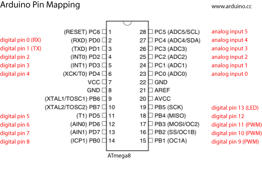
To use this library you need to know the mapping between the Arduino digital pins and the ATmega's pins. This is illustrated in this diagram from the Arduino site:

In this diagram digital pin 2 is labeled "PD2", which means that Arduino digital pin 2 is pin 2 on port D of the ATmega. The complete set of mappings is:
Digital Pin     Port        Pin

0           Port D      0
1           Port D      1
2           Port D      2
3           Port D      3
4           Port D      4
5           Port D      5
6           Port D      6
7           Port D      7
8           Port B      0
9           Port B      1
10          Port B      2
11          Port B      3
12          Port B      4
13          Port B      5
Mapping between the Arduino Mega Digital Pins and the ATmega2560
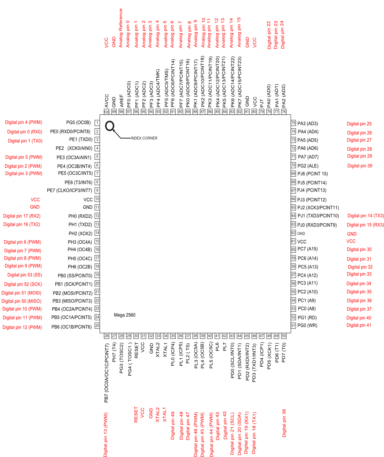
The pin mappings between the Mega and the ATmega2560 is, as expected, much more complex. This is illustrated below:

The complete set of pin mappings is:
Digital Pin Port        Pin Number

0       PORT E      0
1       PORT E      1
2       PORT E      4
3       PORT E      5
4       PORT G      5
5       PORT E      3
6       PORT H      3
7       PORT H      4
8       PORT H      5
9       PORT H      6
10      PORT B      4
11      PORT B      5
12      PORT B      6
13      PORT B      7
14      PORT J      1
15      PORT J      0
16      PORT H      0
17      PORT H      1
18      PORT D      3
19      PORT D      2
20      PORT D      1
21      PORT D      0
22      PORT A      0
23      PORT A      1
24      PORT A      2
25      PORT A      3
26      PORT A      4
27      PORT A      5
28      PORT A      6
29      PORT A      7
30      PORT C      7
31      PORT C      6
32      PORT C      5
33      PORT C      4
34      PORT C      3
35      PORT C      2
36      PORT C      1
37      PORT C      0
38      PORT D      7
39      PORT G      2
40      PORT G      1
41      PORT G      0
42      PORT L      7
43      PORT L      6
44      PORT L      5
45      PORT L      4
46      PORT L      3
47      PORT L      2
48      PORT L      1
49      PORT L      0
50      PORT B      3
51      PORT B      2
52      PORT B      1
53      PORT B      0
The GPIO Pins
To control the GPIO pins, the USEIO and USEGPIO parameters in ArdOSConfig.h must be set to 1.
To access a GPIO pin we first need to set the pin's direction. Two functions are provided to set the pin direction.
Setting Output Pins
The makeOutputPins function configures a set of pins to be output pins. The parameters are:
* port: The port to configure. Valid values are DIRB and DIRD.
* pin: The pins within the ports to configure. The valid valiues for DIRB are from PIN0M to PIN5M, while the valid values for DIRD are from PIN0M to PIN7M.
Usage example:
/*

We want to configure digital pins 3, 4, 9, 12 and 13 to be OUTPUT pins. Pins
3 and 4 correspond to pins 3 and 4 on port D, while pins 9, 12 and 13 correspond to pins 1, 4 and 5 on port B.

*/

...

int main()
{
    ...
    // Configure pins 3 and 4 as output
    makeOutputPins(DIRD, PIN3M | PIN4M);

    // Configure pins 9, 12 and 13 as output
    makeOutputPins(DIRB, PIN1M | PIN4M | PIN5M);
    ...
}
Setting Input Pins
ArdOS provides the makeInputPins to set sets of pins as inputs. The parameters are:
* port: Which ATmega port to use. Valid values are DIRB and DIRD.
* pins: Pins to set as inputs. Valid values for DIRB are from PIN0M to PIN5M, while valid values for DIRD are from PIN0M to PIN7M.
Usage Example:
/*

We want to configure digital pins 1, 5, 10, and 11 to be INPUT pins. Pins
1 and 5 correspond to pins 1 and 5 on port D, while pins 10 and 11 correspond to pins 2 and 3 on port B.

*/

...

int main()
{
    ...
    // Configure pins 1 and 5 as input
    makeInputPins(DIRD, PIN1M | PIN5M);

    // Configure pins 10 and 11 as output
    makeOutputPins(DIRB, PIN2M | PIN3M);
    ...
}
Reading and Writing Pins
ArdOS provides the getInput function for reading pins. Parameters are:
* port: The port to read from. Valid values are INB and IND.
* pin: The pin to read from. Valid values for INB range from 0 to 5, while valid values for IND range from 0 to 7.
This function returns 0 if the read pin has a logical 0 placed on it, and a non-zero value if the read pin has a logical 1 placed on it. The pin must have been set as an input pin using makeInputPins.
ArdOS provides the setOutput function for writing to pins. The parameters are:
* port: The port to write to. Valid values are OUTB and OUTD.
* pin: The pin to write to. Valid values for OUTB range from 0 to 5,
while valid values for OUTD range from 0 to 7.
* value: A 0 to clear the pin, any non-zero value to set it.
The pin must have previously been set as an output pin using makeOutputPins.
Usage Example:
/* We read in pin 5  and switch on or off the LED at pin 12 */

...

    int val=getInput(IND, 5);

    if(val)
        setOutput(OUTB, 4, 1);
    else
        setOutput(OUTB, 4, 0);
...
Reading Analog Inputs
To access the analog input pins, the USEIO and USEADC parameters in ArdOSConfig.h must be set to 1.
ArdOS provides two functions for reading analog inputs. The first is setupADC, which does not take any parameters and needs only to be called once. The second is getADC, which returns the analog value read at the specified pin. The sole parameter to getADC is:
* portnum: The ADC port number to read from. Ranges from 0 to 5 corresponding to analog inputs 0 to 5 on the Arduino.
The getADC function blocks until the Analog to Digital Converter returns a value.
Usage Example:
    int main()
    {
        setupADC();

        while(1)
        {
            // Read from analog input 3
            int val=getADC(3);

            // Process
            ...
        }
    }
Analog Outputs
Section to be completed later. For now you can use analogWrite to read/write the PWM pins. ArdOS does not support analog output on pin 3
Updated